A SRX is a “security device”, or as we call it conventionally, a firewall. Modern layer-3 firewalls route packets just like a router, but unlike a router, a firewall can organize packets into connections (flows) and run ACLs on the entire flow. This unique functionality is the fundamental building block of every “advanced” security feature offered by a firewall: dynamic NAT (PAT/NPT), zone-based firewall (ZBFW), ACLs for in or out connections only, L7 filtering, etc. For the connection (flow) tracking to work, all the packets in a connection must go through the same device, and the 5-tuple of all the packets in a connection must be of expected values, which usually means:
- The packets from A to B and the packets from B to A must all go through the firewall at some point
- There shouldn’t be single-sided stateless NAT happening on the route
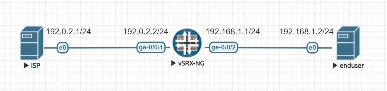
This was never an issue when everyone was single-homed and all the routers had only one routing table. But not today. SRXs now have built-in support for virtual routers which can create an asymmetric flow easily. Let’s look at this simplified topology:
First of all, we need to make sure the SRX works in flow mode. If it is in the packet mode, then it acts like a traditional packet-forwarding router and all the things we are talking about it today does not apply at all.
|
1 2 3 4 |
root@lan-gw> show security flow status Flow forwarding mode: Inet forwarding mode: flow based Inet6 forwarding mode: flow based |
For flexibility (i.e. we will have multiple LAN tenants and we want to isolate them later), we put the ISP and the LAN in different virtual routers:
|
1 2 3 4 5 6 7 8 9 10 11 12 13 14 15 16 17 18 19 20 |
# VR at the ISP side set routing-instances ISP instance-type virtual-router set routing-instances ISP interface ge-0/0/1.0 set routing-instances ISP routing-options rib ISP.inet.0 static defaults install set routing-instances ISP routing-options rib ISP.inet.0 static defaults resolve set routing-instances ISP routing-options rib ISP.inet.0 static route 0.0.0.0/0 next-hop 192.0.2.1 set routing-instances ISP routing-options auto-export set interfaces ge-0/0/1.0 family inet address 192.0.2.2/24 # VR at the LAN side set routing-instances LAN instance-type virtual-router set routing-instances LAN interface ge-0/0/2.0 set routing-instances LAN routing-options auto-export set interfaces ge-0/0/2.0 family inet address 192.168.1.1/24 # import all ISP VR routes into LAN VR set routing-instances LAN routing-options instance-import VR_ISP_TO_LAN set policy-options policy-statement VR_ISP_TO_LAN term 1 from instance ISP set policy-options policy-statement VR_ISP_TO_LAN term 1 then accept set policy-options policy-statement VR_ISP_TO_LAN term FINAL then reject |
This created 2 IPv4 routing tables: ISP.inet.0 and LAN.inet.0, then assigned the two interfaces to their corresponding routing tables. Then we also imported all the routers in the ISP.inet.0 table into the LAN.inet.0 table. Let’s see if the routing tables contain the routes we expected:
|
1 2 3 4 5 6 7 8 9 10 11 12 13 14 15 16 17 18 19 20 21 22 23 24 25 |
root@lan-gw> show route ISP.inet.0: 3 destinations, 3 routes (3 active, 0 holddown, 0 hidden) + = Active Route, - = Last Active, * = Both 0.0.0.0/0 *[Static/5] 00:16:39 > to 192.0.2.1 via ge-0/0/1.0 192.0.2.0/24 *[Direct/0] 00:16:39 > via ge-0/0/1.0 192.0.2.2/32 *[Local/0] 00:16:39 Local via ge-0/0/1.0 LAN.inet.0: 5 destinations, 5 routes (5 active, 0 holddown, 0 hidden) + = Active Route, - = Last Active, * = Both 0.0.0.0/0 *[Static/5] 00:14:43 > to 192.0.2.1 via ge-0/0/1.0 192.0.2.0/24 *[Direct/0] 00:14:43 > via ge-0/0/1.0 192.0.2.2/32 *[Local/0] 00:14:43 Local via ge-0/0/1.0 192.168.1.0/24 *[Direct/0] 00:18:48 > via ge-0/0/2.0 192.168.1.1/32 *[Local/0] 00:18:48 Local via ge-0/0/2.0 |
So, if we ping 192.168.1.2 from a device on the ISP side (e.g. 192.0.2.1), it should not go through the SRX. This is because if we send a packet destinated to 192.168.1.2 into SRX’s interface ge-0/0/1.0, and since ge-0/0/1.0 is associated to the routing table ISP.inet.0, there are no detailed route to 192.168.1.2, thus the packet is routed back to ge-0/0/1.0 thanks to the default route.
Let’s put on the router hat and think another question: what will happen if we ping 192.0.2.1 from the LAN side (e.g. 192.168.1.2)? Obviously the ICMP echo request packet will go through the SRX since we do have routes to 192.0.2.0/24 in routing table LAN.inet.0 pointing to the correct interface, but the ICMP echo reply packet would not go through just like the first case, right? Well, let’s try it out.
|
1 2 3 4 5 6 7 |
root@enduser:~# ping -c 1 192.0.2.1 PING 192.0.2.1 (192.0.2.1) 56(84) bytes of data. 64 bytes from 192.0.2.1: icmp_seq=1 ttl=63 time=1.62 ms --- 192.0.2.1 ping statistics --- 1 packets transmitted, 1 received, 0% packet loss, time 0ms rtt min/avg/max/mdev = 1.616/1.616/1.616/0.000 ms |
Well, that’s a little unexpected. But why? It’s because the SRX’s flow based forwarding process is a little different from a router’s packet based forwarding process. Let’s look at our ICMP flow:
|
1 2 3 4 5 6 7 8 9 10 11 12 13 14 15 16 17 18 19 20 21 22 23 24 25 26 |
root@lan-gw> show security flow session extensive protocol icmp Session ID: 1842, Status: Normal Flags: 0x80000040/0x0/0x0/0x800003 Policy name: default-policy-logical-system-00/2 Source NAT pool: Null Dynamic application: junos:UNKNOWN, Encryption: Unknown Application traffic control rule-set: INVALID, Rule: INVALID Maximum timeout: 4, Current timeout: 2 Session State: Valid Start time: 2681, Duration: 2 In: 192.168.1.2/1 --> 192.0.2.1/744;icmp, Conn Tag: 0x0, Interface: ge-0/0/2.0, Session token: 0x6008, Flag: 0x21 Route: 0xb0010, Gateway: 192.168.1.2, Tunnel: 0 Port sequence: 0, FIN sequence: 0, FIN state: 0, Pkts: 1, Bytes: 84 Out: 192.0.2.1/744 --> 192.168.1.2/1;icmp, Conn Tag: 0x0, Interface: ge-0/0/1.0, Session token: 0x5007, Flag: 0x20 Route: 0xa0010, Gateway: 192.0.2.1, Tunnel: 0 Port sequence: 0, FIN sequence: 0, FIN state: 0, Pkts: 1, Bytes: 84 Total sessions: 1 |
A flow consists of two match conditions for two packet directions. The “In” condition is taken from the first packet of a flow received by SRX, and the “Out” condition is derived from all the packet transformation rules. (NOTE: Everything displayed here with a direction assumes the current device is receiving the traffic. e.g. If you need to see the gateway of the “Out” direction, you need to look at the line after “In”.) This is how connection tracking works under the hood. In Junos, either direction will be associated with a route in the active routing table. By default, the reverse route lookup mode is “flow mode”, which causes the route associated with the “Out” direction is also calculated from the routing table of the “In” interface. This mode breaks the assumption that a packet should be forwarded according to the routing table the receiving interface is associated to, but flow symmetry is easily achieved.
Now let’s try set the reverse route lookup mode to “packet mode”:
|
1 |
set security flow advanced-options reverse-route-packet-mode-vr |
You can verify yourself the routing table is the same, but the LAN device would not be able to ping the ISP device anymore. If you look at the flow session table again, you should see the associated route for the “Out” direction is now 0x0, denoting a route lookup failure.
|
1 2 3 4 5 6 7 8 9 10 11 12 13 14 15 16 17 18 19 20 21 22 23 24 25 26 |
root@lan-gw> show security flow session extensive protocol icmp Session ID: 2365, Status: Normal Flags: 0x40/0x0/0x0/0x3 Policy name: default-policy-logical-system-00/2 Source NAT pool: Null Dynamic application: junos:UNKNOWN, Encryption: Unknown Application traffic control rule-set: INVALID, Rule: INVALID Maximum timeout: 60, Current timeout: 6 Session State: Valid Start time: 3477, Duration: 1 In: 192.168.1.2/1 --> 192.0.2.1/754;icmp, Conn Tag: 0x0, Interface: ge-0/0/2.0, Session token: 0x6008, Flag: 0x21 Route: 0x0, Gateway: 192.168.1.2, Tunnel: 0 Port sequence: 0, FIN sequence: 0, FIN state: 0, Pkts: 1, Bytes: 84 Out: 192.0.2.1/754 --> 192.168.1.2/1;icmp, Conn Tag: 0x0, Interface: ge-0/0/1.0, Session token: 0x5007, Flag: 0x20 Route: 0xa0010, Gateway: 192.0.2.1, Tunnel: 0 Port sequence: 0, FIN sequence: 0, FIN state: 0, Pkts: 0, Bytes: 0 Total sessions: 1 |
If we do a packet capture on the ISP router, we should see it successfully receiving the echo request packet and sending out the echo reply packet. The reply packet will be discarded by the SRX (because of the route lookup failure) and never reach its intended destination, though.
|
1 2 3 4 5 6 |
root@ISP:~# tcpdump -ni ens3 icmp [ 4174.166928] device ens3 entered promiscuous mode tcpdump: verbose output suppressed, use -v or -vv for full protocol decode listening on ens3, link-type EN10MB (Ethernet), capture size 262144 bytes 09:14:46.237810 IP 192.168.1.2 > 192.0.2.1: ICMP echo request, id 757, seq 130, length 64 09:14:46.237852 IP 192.0.2.1 > 192.168.1.2: ICMP echo reply, id 757, seq 130, length 64 |
In this configuration, you can still ping the SRX’s ISP-facing interface IP from the LAN device:
|
1 2 3 4 5 6 7 |
root@enduser:~# ping -c 1 192.0.2.2 PING 192.0.2.2 (192.0.2.2) 56(84) bytes of data. 64 bytes from 192.0.2.2: icmp_seq=1 ttl=64 time=0.985 ms --- 192.0.2.2 ping statistics --- 1 packets transmitted, 1 received, 0% packet loss, time 0ms rtt min/avg/max/mdev = 0.985/0.985/0.985/0.000 ms |
Why this is possible is trivial and left as an exercise to the reader.
Conclusion
One that is used to the VRFs on the routers might be confused by the default reverse route lookup mode when using SRXs for the first time. But the ability to change how returning packet is routed is particularly useful when familiarized. It allows us to easily achieve flow symmetry in a multi-VR environment without adding a lot complexity on route import/export policies, and it can simulate simple ZBFW functionality with pure routing table designs.
Appendix
The lab topology is verified under Junos OS 18.4R3.3 (vSRX3) and 20.1R1-S1.2 (SRX300).
For simplicity, the configuration above is not complete. If you are trying to replicate the lab topology, you also need the following configuration:
|
1 2 3 4 5 6 7 8 9 10 |
set system root-authentication plain-text-password set system host-name lan-gw set system no-redirects set security policies default-policy permit-all set security zones security-zone ISP host-inbound-traffic system-services any-service set security zones security-zone ISP host-inbound-traffic protocols all set security zones security-zone ISP interfaces ge-0/0/1.0 set security zones security-zone LAN host-inbound-traffic system-services any-service set security zones security-zone LAN host-inbound-traffic protocols all set security zones security-zone LAN interfaces ge-0/0/2.0 |
References:
Pingback: Access Services on the Router from VRF on RouterOS 6 | Drown in Codes