Cisco Aironet 1800i is a cute little device that is just a little smaller than my hand. They are light in weight, not very hot (not a good replacement of the old 3502i model if you also have a cat around your home) and require less power to operate. I recently got one 1800i in my room, so I’d like to write a little about this model since it is so different from the old PowerPC-based ones.
Networking Specs
Compiled from Cisco Aironet 1800i Access Point Getting Started Guide:
- Indoors deployment only
- Embedded two 2.4G + 5.8G dual-band antennas (omnidirectional, [email protected], [email protected])
- 2.4G: 2SS SU-MIMO
- 5.8G: 2SS MU-MIMO (802.11ac Wave 2, a.k.a. Wi-Fi 5)
- One 1Gbps Ethernet uplink
- Powered by either PoE (802.3af/at) or MicroUSB (5V 1.5A)
- CAPWAP (Thin) mode only, no Autonomous (Fat) capability (reads: must be used with a controller)
- Does NOT support wireless mesh
- Does NOT support Bluetooth beacon
Note that the description of LED patterns in the Getting Started Guide is wrong.
There is an Aironet 1800s model which is based on the same hardware but can only act as a wireless environment sensor/monitor and cannot be used as an AP. The 1800s require a cloud subscription to work properly. Whether the 1800s can cross-flash a 1800i’s firmware is unknown. Considering that 1800i is not even listed in the 1800 series portfolio, I guess it is a last-minute decision to rebrand/reuse the 1800s’ hardware and make a low-end AP out of it.
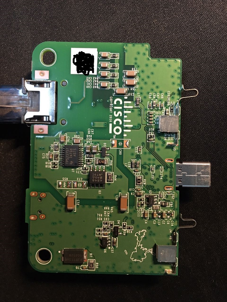
Hardware Specs
- SoC: Qualcomm IPQ4019 (Quad-core Cortex A7 @717MHz)
- Memory: SKhynix 512MiB
- Storage: Macronix MX25L3205D 4MiB SPI Flash
- Storage: Spansion (
Cypress Semiconductor) S34ML01G200TF100 16MiB NAND - Ethernet PHY: Qualcomm Atheros AR8035
- 2.4G RF Frontend: Skyworks SKY85325-11
- 5.8G RF Frontend: Skyworks SKY85717-21
- Bluetooth: TI CC2640 (not used)
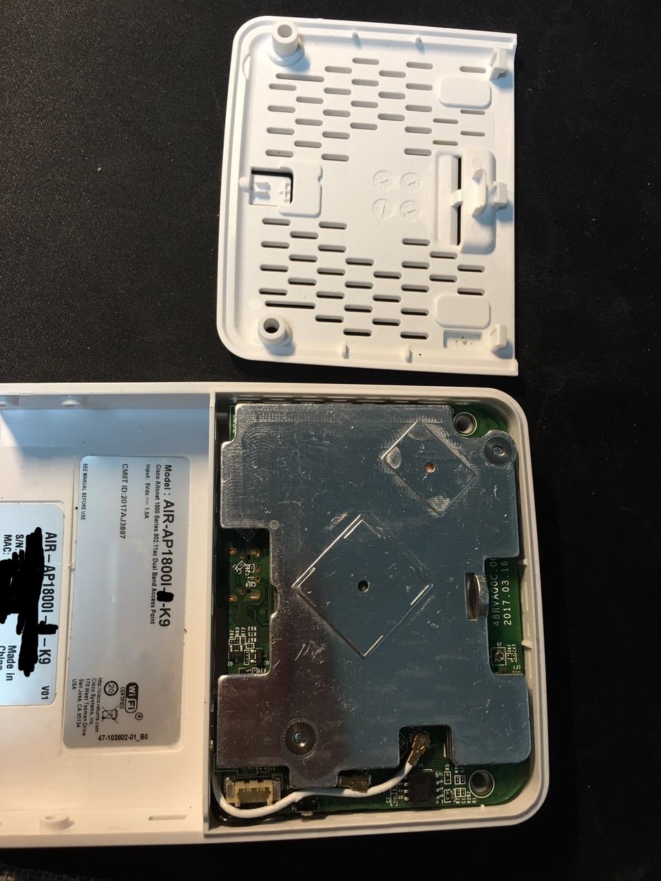
The hardware is essentially 2 pieces, one main body with the SoC, SKU AIR-AP1800I-x-K9 (x is your country code); one extension module with the Ethernet port and the power conversion things, SKU AIR-MOD-POE . They can be detached without tool (the mechanical connection is very firm).
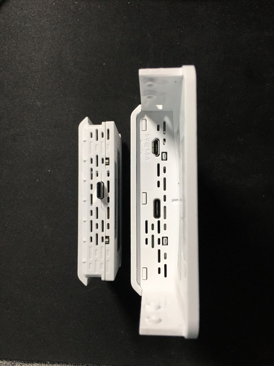
The PoE module (left) and the main body (right)
The two modules are connected with a non-standard USB C port and two insert detection pins. (Details below.)
For Aironet 1800s, there are other extension modules available, namely AIR-MOD-USB-xx and AIR-MOD-AC.
PoE Module
The PoE Module accepts an 1Gbps Ethernet connection with 802.3af/at or MicroUSB 5V input, and transfers power and data to the main module.
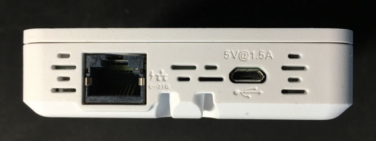
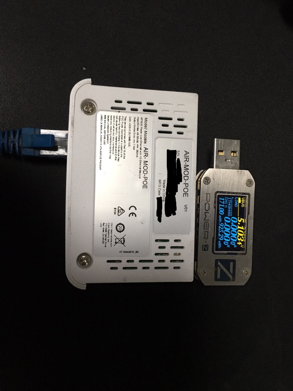
You can charge a 3rd party device on the module with PoE (5V passive power only, no support for any quick charge protocols so the 3rd party device may limit itself to 0.5A), but it is not a USB to Ethernet adapter (USB C data pins are used to connect Ethernet PHY and MAC) so you cannot use the module as a USB device on any 3rd party USB host. (WARNING: plugging any USB host/device onto that module might damage both of them; although this does not happen in my experiment, I’m not responsible for any damage to your devices.)
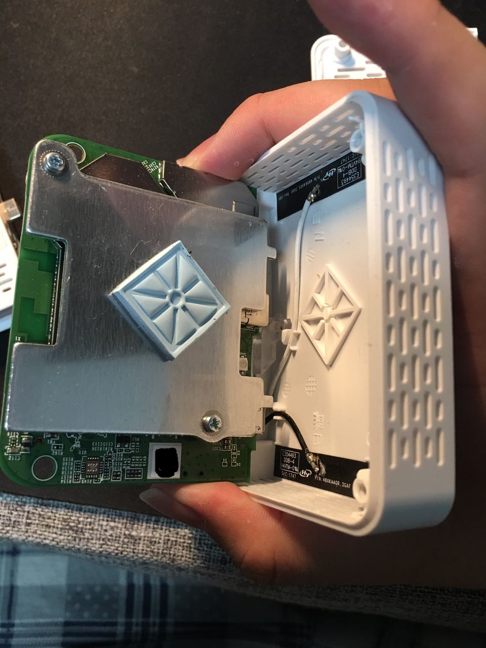
2 Philips screws hold its case. After removing them, the PCB can be easily revealed. Please be careful not to bend the insert detection terminals.
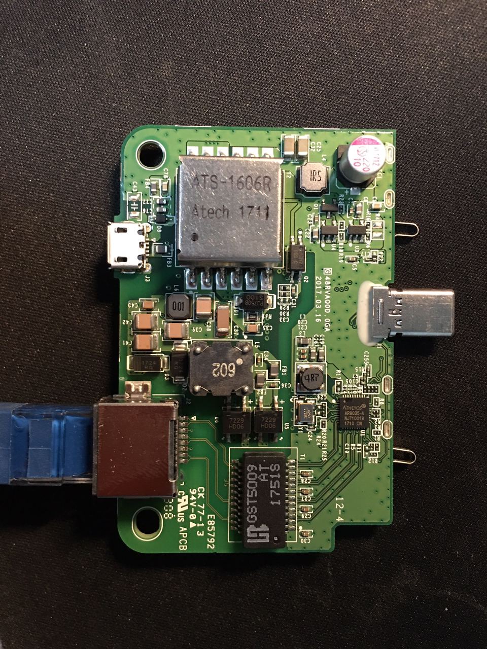
The insert detection terminals are wired on the PoE module; they touch one of the metal heatsink plates on the other module when inserted.
Main Body
The main body contains the SoC and all wireless components. Two Philips screws hold the back cover. On the back of the PCB resides the serial port, the reset button, the SPI flash, two coaxial antenna connectors for Wi-Fi and one smaller unconnected coaxial connector for Bluetooth. Other major components are hidden under the big metal shield.
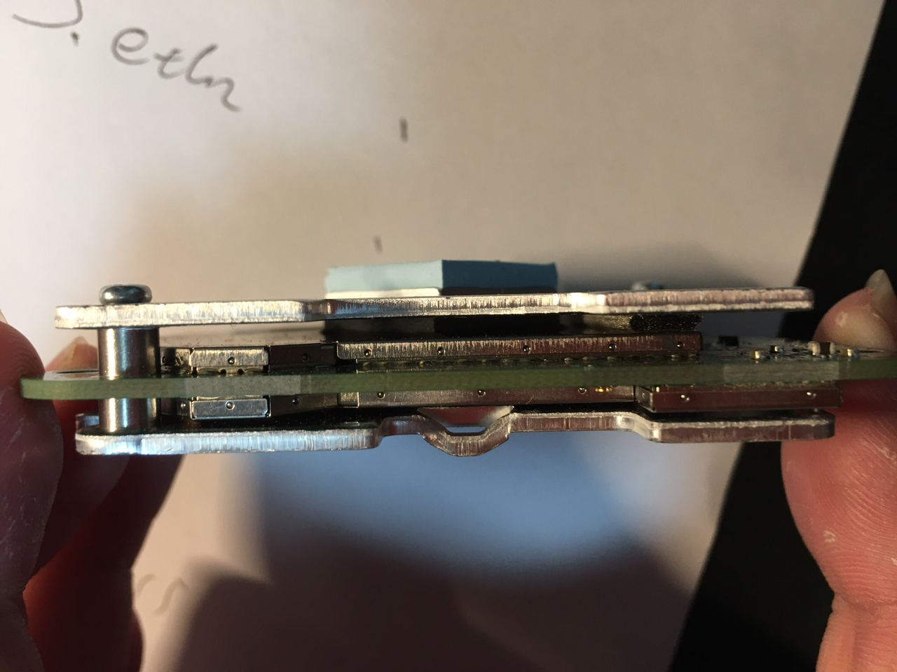
Disconnect the two antennas, then use the ring structure on the metal heatsink as a fulcrum to raise the board. On the front side of the board we have two more metal shields and a tri-color LED.
Side-view of the PCB sandwich:
When assembling the main module, first put the PCB into the case, then insert the PoE module before screwing the back cover. Otherwise the USB C port might not align.
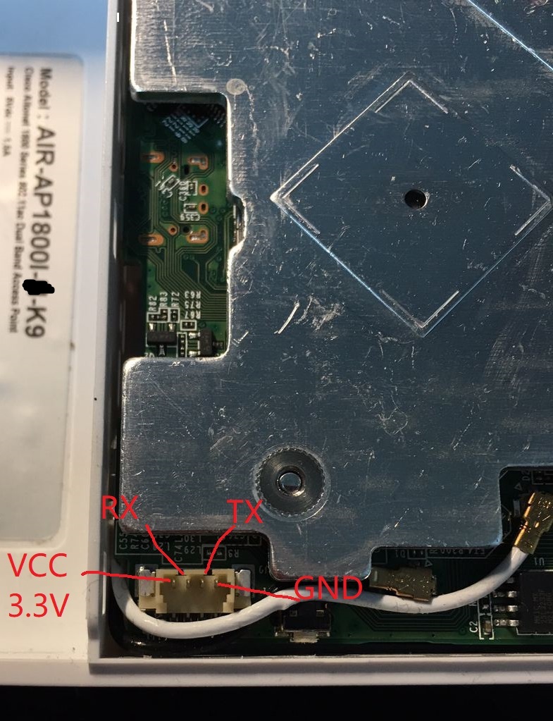
Serial Port
The serial port is one with an absolute propriety (TM) connector. Cisco sells the AIR-CONSADPT= to convert it to a traditional RJ45-like RS232-level port to achieve compatibility with the good old USB RS232 serial cable, but this converter is not globally available and is rarely seen on second hand markets. Luckily, you can make yourself a serial cable out of simple parts. What you need is:
- A JST GH (1.25mm/0.049in) connector with breakout cables (it might not fit well in the port, but most of GH connectors on the market can work with some additional force)
- A 3.3V (TTL level, UART) serial to USB adapter board
- Some 2.54mm female wires that connects to the serial to USB adapter
Connecter definition (left to right, the Ethernet port towards the left):
- VCC, 3.3V (for powering the Cisco adapter; do not connect it)
- RX
- TX
- GND
Connect the AP and the USB serial converter (you might need some soldering), GND to GND, RX to TX and TX to RX. If your USB serial converter have voltage/level selection jumper or switch, select 3.3V. You should end up with something like this (please do proper isolation between naked wires, don’t be like me):
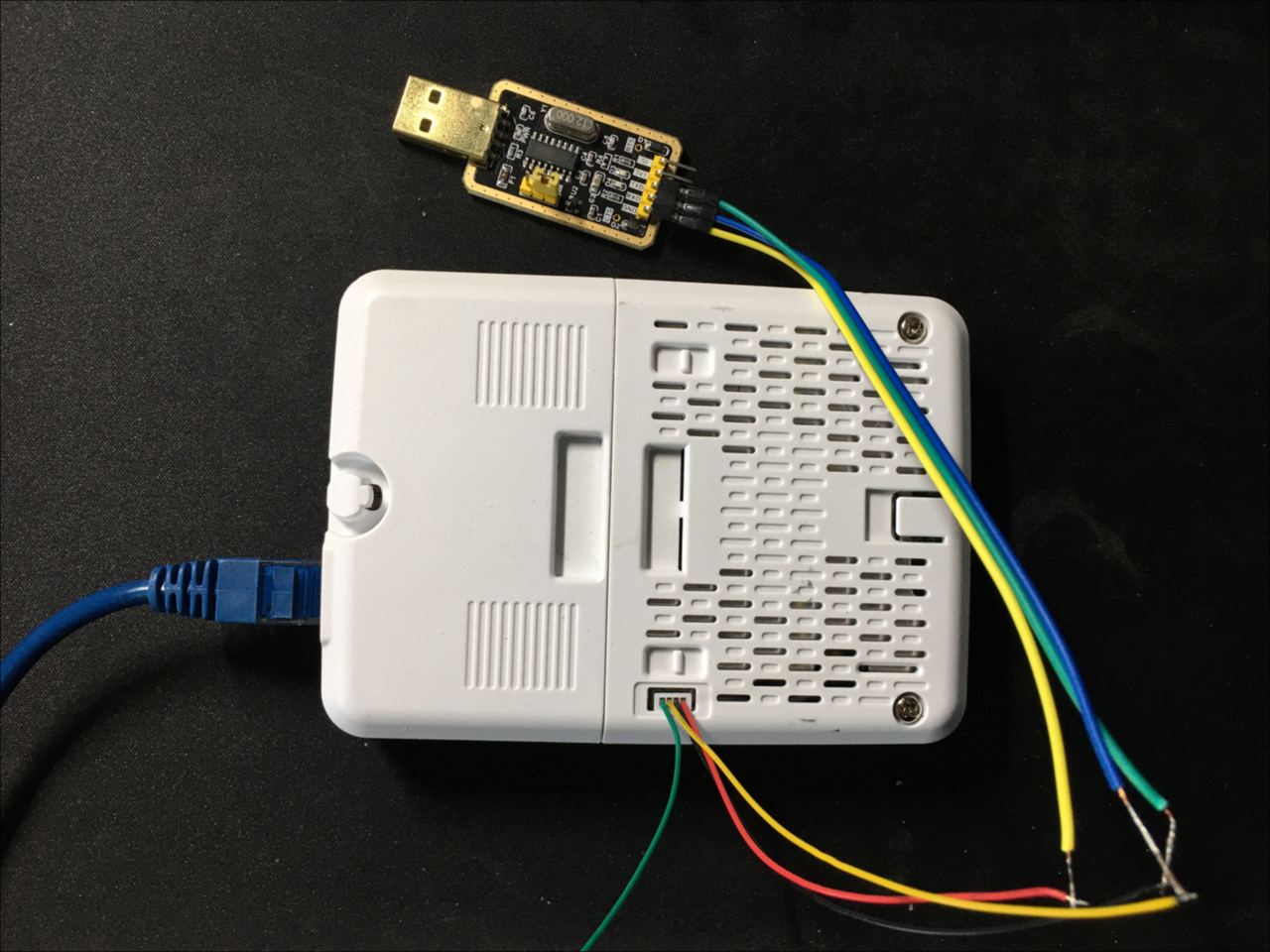
Plug the USB serial converted to your computer. Set your serial port software to 9600,8N1, or:
- Baud rate: 9600
- Parity: none
- Stop bit: 1
- Data bits: 8
- Flow control: XON/XOFF or none
and profit. The default username and password are both Cisco.
Factory image (version 8.10.130.0) boot log, if anyone is interested:
|
1 2 3 4 5 6 7 8 9 10 11 12 13 14 15 16 17 18 19 20 21 22 23 24 25 26 27 28 29 30 31 32 33 34 35 36 37 38 39 40 41 42 43 44 45 46 47 48 49 50 51 52 53 54 55 56 57 58 59 60 61 62 63 64 65 66 67 68 69 70 71 72 73 74 75 76 77 78 79 80 81 82 83 84 85 86 87 88 89 90 91 92 93 94 95 96 97 98 99 100 101 102 103 104 105 106 107 108 109 110 111 112 113 114 115 116 117 118 119 120 121 122 123 124 125 126 127 128 129 130 131 132 133 134 135 136 137 138 139 140 141 142 143 144 145 146 147 148 149 150 151 152 153 154 155 156 157 158 159 160 161 162 163 164 165 166 167 168 169 170 171 172 173 174 175 176 177 178 179 180 181 182 183 184 185 186 187 188 189 190 191 192 193 194 195 196 197 198 199 200 201 202 203 204 205 206 207 208 209 210 211 212 213 214 215 216 217 218 219 220 221 222 223 224 225 226 227 228 229 230 231 232 233 234 235 236 237 238 239 240 241 242 243 244 245 246 247 248 249 250 251 252 253 254 255 256 257 258 259 260 261 262 263 264 265 266 267 268 269 270 271 272 273 274 275 276 277 278 279 280 281 282 283 284 285 286 287 288 289 290 291 292 293 294 295 296 297 298 299 300 301 302 303 304 305 306 307 308 309 310 311 312 313 314 315 316 317 318 319 320 321 322 323 324 325 326 327 328 329 330 331 332 333 334 335 336 337 338 339 340 341 342 343 344 345 346 347 348 349 350 351 352 353 354 355 356 357 358 359 360 361 362 363 364 365 366 367 368 369 370 371 372 373 374 375 376 377 378 379 380 381 382 383 384 385 386 387 388 389 390 391 392 393 394 395 396 397 398 399 400 401 402 403 404 405 406 407 408 409 410 411 412 413 414 415 416 417 418 419 420 421 422 423 424 425 426 427 428 429 430 431 432 433 434 435 436 437 438 439 440 441 442 443 444 445 446 447 448 449 450 451 452 453 454 455 456 457 458 459 460 461 462 |
Board type: AP1800I smem ram ptable found: ver: 1 len: 3 U-Boot 2012.07 (btldr release 51) (Oct 29 2019 - 06:43:09) This product contains some software licensed under the "GNU General Public License, version 2" provided with ABSOLUTELY NO WARRANTY under the terms of "GNU General Public License, version 2", available here: http://www.gnu.org/licenses/old-licenses/gpl-2.0.html DRAM: 510 MiB Nand: Detected ONFI AMD NAND 128MiB 3,3V 8-bit NAND ECC=4 ECC_THRESHOLD(NAND ECC-1)=3 SF: Detected MX25L3205D with page size 4 KiB, total 4 MiB MFG data loaded Scanning shenv data blocks Total valid parts=4 Active shenv part[1:0], write_counter=51 machid: 8010001 Net: Cradle/PHY Detected. MAC0 addr:02:00:00:00:00:00 AR8033 PHY 0 PHY ID1: 0x4d PHY ID2: 0xd072 ipq40xx_ess_sw_init done Auto boot mode, use bootipq directly Hit ESC key to stop autoboot: 0 Specified BOOT: part2 Booting from part2 Read 1024 bytes from volume part2 to 88000000 Read 37237664 bytes from volume part2 to 88000000 Signature returns 0 Image signing verification success, continue to run... bootm 0x88000400 ## Booting kernel from Legacy Image at 88000400 ... ## Loading init Ramdisk from multi component Legacy Image at 88000400 ... ## Flattened Device Tree from multi component Image at 88000400 Booting using the fdt at 0x8a379988 Loading Ramdisk to 9dc80000, end 9fdff388 ... OK Loading Device Tree to 9dc73000, end 9dc7f217 ... OK no such device nand0 Using machid 0x8010001 from environment Starting image ... [01/01/1970 00:00:34.9799] Linux version 3.14.43 (aut@cheetah-build4) (gcc version 4.7.1 (OpenWrt GCC 4.7.1 r48430) ) #1 SMP PREEMPT Tue Jul 28 23:53:37 PDT 2020 [01/01/1970 00:00:35.1399] CPU: ARMv7 Processor [410fc075] revision 5 (ARMv7), cr=10c5387d [01/01/1970 00:00:35.2399] CPU: PIPT / VIPT nonaliasing data cache, VIPT aliasing instruction cache [01/01/1970 00:00:35.3399] Machine model: Cisco 11ac Wave2 Wifi Access Point [01/01/1970 00:00:35.4199] Memory policy: Data cache writealloc [01/01/1970 00:00:35.4899] Kernel command line: console=ttyMSM0,9600n8 ubi.mtd=0 root=/dev/ram activepart=part2 activeboot=0 wdgtriggered=0 board_sku=8 clk_ignore_unused [01/01/1970 00:00:35.6699] CPU1: Booted secondary processor [01/01/1970 00:00:35.7299] CPU2: Booted secondary processor [01/01/1970 00:00:35.7999] CPU3: Booted secondary processor [01/01/1970 00:00:35.8599] buginf tty flushing thread started, ttyport=9d52c400 [01/01/1970 00:00:36.1399] msm_nand_flash_onfi_probe: CRC Check failed on param page [*01/01/1970 00:00:39.1577] buginf() enabled. [*01/01/1970 00:00:39.1873] Made it into bootsh: Jul 29 2020 00:16:46 T-cbfc6f1f9918f53aa2f774f4ee9f9aefab116a16-gcbfc6f1f-aut [01/01/1970 00:00:58.8299] audit_printk_skb: 105 callbacks suppressed [01/01/1970 00:01:17.8899] audit_printk_skb: 36 callbacks suppressed Welcome to Cisco. Usage of this device is governed by Cisco's End User License Agreement, available at: http://www.cisco.com/c/en/us/td/docs/general/warranty/English/EU1KEN_.html. Restricted Rights Legend Use, duplication, or disclosure by the Government is subject to restrictions as set forth in subparagraph (c) of the Commercial Computer Software - Restricted Rights clause at FAR sec. 52.227-19 and subparagraph (c) (1) (ii) of the Rights in Technical Data and Computer Software clause at DFARS sec. 252.227-7013. Cisco Systems, Inc. 170 West Tasman Drive San Jose, California 95134-1706 This product contains cryptographic features and is subject to United States and local country laws governing import, export, transfer and use. Delivery of Cisco cryptographic products does not imply third-party authority to import, export, distribute or use encryption. Importers, exporters, distributors and users are responsible for compliance with U.S. and local country laws. By using this product you agree to comply with applicable laws and regulations. If you are unable to comply with U.S. and local laws, return this product immediately. A summary of U.S. laws governing Cisco cryptographic products may be found at: http://www.cisco.com/wwl/export/crypto/tool/stqrg.html If you require further assistance please contact us by sending email to This product contains some software licensed under the "GNU General Public License, version 2" provided with ABSOLUTELY NO WARRANTY under the terms of "GNU General Public License, version 2", available here: http://www.gnu.org/licenses/old-licenses/gpl-2.0.html This product contains some software licensed under the "GNU Library General Public License, version 2" provided with ABSOLUTELY NO WARRANTY under the terms of "GNU Library General Public License, version 2", available here: http://www.gnu.org/licenses/old-licenses/lgpl-2.0.html This product contains some software licensed under the "GNU Lesser General Public License, version 2.1" provided with ABSOLUTELY NO WARRANTY under the terms of "GNU Lesser General Public License, version 2.1", available here: http://www.gnu.org/licenses/old-licenses/lgpl-2.1.html This product contains some software licensed under the "GNU General Public License, version 3" provided with ABSOLUTELY NO WARRANTY under the terms of "GNU General Public License, Version 3", available here: http://www.gnu.org/licenses/gpl.html. This product contains some software licensed under the "GNU Affero General Public License, version 3" provided with ABSOLUTELY NO WARRANTY under the terms of "GNU Affero General Public License, version 3", available here: http://www.gnu.org/licenses/agpl-3.0.html. [ OK ] Reached target Cisco File Systems (Pre). [ OK ] Reached target Timers. [ OK ] Created slice -.slice. [ OK ] Listening on Delayed Shutdown Socket. [ OK ] Reached target Sockets. [ OK ] Created slice system.slice. Starting Cisco UBIFS reformat/mount... [ OK ] Created slice system-serial\x2dgetty.slice. [ OK ] Reached target Slices. [ OK ] Started Cisco UBIFS reformat/mount. Starting Cisco early mount... [ OK ] Started Cisco early mount. [ OK ] Reached target Local File Systems (Pre). Starting Cisco fips check... Starting Cisco system time setup... Starting Cisco seed generation... [*04/10/2018 23:59:59.0533] Last reload time: Oct 2 10:37:06 2020 [*10/02/2020 10:37:06.0014] Setting system time Fri Oct 2 10:37:06 UTC 2020 [*10/02/2020 10:37:06.0583] GCM-128 POST passed [*10/02/2020 10:37:06.0584] GCM-256 POST passed Starting Cisco platform file generation... [ OK ] Started Cisco fips check. [*10/02/2020 10:37:06.3177] /etc/init.d/generate_platforms: line 1: plat_get_usb_admin_state: not found [ OK ] Started Cisco system time setup. [ OK ] Started Cisco seed generation. [ OK ] Started Cisco platform file generation. [ OK ] Reached target Local File Systems. Starting Cisco S10 boot service... Starting Security Auditing Service... [*10/02/2020 10:37:06.8179] parameter passed without an option given Starting Cisco pkg install service... [ OK ] Started Cisco system time saving. Starting Cisco system time saving... Starting Cisco act2 check... [*10/02/2020 10:37:07.1495] === 5G radio domain is 51, COPY 5G BDF files from non_ETSI_BDF folder === [*10/02/2020 10:37:07[ OK ] Started Security Auditing Service. [ OK ] Started Cisco act2 check. [10/02/2020 10:37:06.4599] ramoops: Unknown symbol encode_rs8 (err 0) [10/02/2020 10:37:06.5199] ramoops: Unknown symbol decode_rs8 (err 0) [10/02/2020 10:37:06.5999] ramoops: Unknown symbol init_rs (err 0) [ OK ] Started Cisco S10 boot service. Starting Cisco watchdog... Starting Cisco nolan service... Starting Cisco nss service... [ OK ] Started Cisco watchdog. [ OK ] Started Cisco nolan service. [ OK ] Started Cisco nss service. [*10/02/2020 10:37:07.4931] Active version: 8.10.130.0 [*10/02/2020 10:37:07.5011] Backup version: 8.5.103.0 [*10/02/2020 10:37:07.8696] [*10/02/2020 10:37:07.8696] led pattern module start [*10/02/2020 10:37:07.9269] Loading caldata from mtd2 [*10/02/2020 10:37:08.6266] ess-switch DT exist! [*10/02/2020 10:37:08.6267] switchreg_base_addr: 0xc000000 [*10/02/2020 10:37:08.6267] switchreg_size: 0x80000 [*10/02/2020 10:37:08.6267] switch_access_mode: local bus [*10/02/2020 10:37:08.6268] wan bmp:0x20 [*10/02/2020 10:37:08.6268] ess-psgmii DT exist! [*10/02/2020 10:37:08.6268] mac mode=3 [*10/02/2020 10:37:08.6268] current mac mode = 3 [*10/02/2020 10:37:08.6269] current dts led_source_num is 5 [*10/02/2020 10:37:08.6269] mdio DT exist! [*10/02/2020 10:37:08.6270] ssdk_plat_init start [*10/02/2020 10:37:08.6272] enable ess clk [*10/02/2020 10:37:08.7376] reset ok in probe! [*10/02/2020 10:37:08.7388] PHY ID is 0x4dd072 [*10/02/2020 10:37:08.8255] Dakota Chip version 0x1401 [*10/02/2020 10:37:08.8258] [*10/02/2020 10:37:08.8258] QCA Switch config done - default in CPU switching. [*10/02/2020 10:37:08.8369] gcc map success! [*10/02/2020 10:37:08.8820] qca-ssdk module init succeeded! [*10/02/2020 10:37:08.8822] [*10/02/2020 10:37:08.8823] QCA Switch config done - default in CPU switching. [*10/02/2020 10:37:09.1695] crypto worker thread started [*10/02/2020 10:37:09.1774] crypto worker thread started [*10/02/2020 10:37:09.3088] pid 3112's current affinity mask: f [*10/02/2020 10:37:09.3088] pid 3112's new affinity mask: e [*10/02/2020 10:37:09.3169] pid 3111's current affinity mask: f [*10/02/2020 10:37:09.3170] pid 3111's new affinity mask: e [*10/02/2020 10:37:09.5726] Current value of FACTORY_RESET=0 [*04/10/2018 23:59:59.0380] Last reload time: Oct 2 10:37:06 2020 [*10/02/2020 10:37:06.0010] Setting system time Fri Oct 2 10:37:06 UTC 2020 [*10/02/2020 10:37:06.1568] device wired0 entered promiscuous mode [*10/02/2020 10:37:07.1993] Last reload reason : 0: unknown [ OK ] Started Cisco pkg install service. Starting Cisco S15platform... Starting Cisco Kclick... [ OK ] Started Cisco S15platform. [ OK ] Started Cisco Kclick. Starting Cisco Kclick... Starting Cisco ME service... Starting Cisco certificate create service... [ OK ] Started Cisco ME service. [ OK ] Started Cisco Kclick. Starting rsyslog client... [*10/02/2020 10:37:13.7104] stile module dp init successfully [*10/02/2020 10:37:13.7104] NBAR Label:BLD_POLARIS_DEV_LATEST_20200414_053707 Module timestamp: Jul 29 2020 at 00:06:05 User: ttaichol [*10/02/2020 10:37:22.7431] Loading sha2... [*10/02/2020 10:37:22.7527] Dumpping sha1... [*10/02/2020 10:37:23.2867] [*10/02/2020 10:37:23.2867] Click sched monitor: schedulers = 3 [*10/02/2020 10:37:23.6040] Loading MIC cert and key [*10/02/2020 10:37:23.6128] Dumpping sha2... Starting Cisco syslog service... Starting Cisco S16platfomm... [ OK ] Started rsyslog client. [ OK ] Started Cisco syslog service. [ OK ] Started Cisco S16platfomm. Starting Cisco synclogd... [ OK ] Started Cisco synclogd. [ OK ] Started Cisco certificate create service. [ OK ] Started Cisco Tam service. Starting Cisco Tam service... Starting Cisco certtime service... [ OK ] Started Cisco certtime service. [ OK ] Reached target System Initialization. [ OK ] Reached target Paths. [ OK ] Reached target Basic System. Starting Cisco klogd... Starting Cisco printkd... Starting Clean Air daemon... Starting Fast CGI daemon... Starting AP Trace daemon... Starting Cisco led service... [ OK ] Started Serial Getty on ttyS0. Starting Serial Getty on ttyS0... [*10/02/2020 10:37:24.4146] Loading MIC cert and key [ OK ] Reached target Login Prompts. Starting capwapd... Starting OpenSSH server daemon... Starting Cisco kexec... [ OK ] Started System Monitor service. Starting System Monitor service... Starting Cisco rtd service... Starting Hostapd process... Starting WCPD process... [ OK ] Started NTP_PROC daemon. Starting NTP_PROC daemon... Starting gRPC server daemon... Starting Cisco brain service... [ OK ] Started Cisco led service. [ OK ] Started Cisco kexec. [ OK ] Started Cisco klogd. [ OK ] Started Cisco printkd. [ OK ] Started Fast CGI daemon. [ OK ] Started AP Trace daemon. [ OK ] Started Cisco rtd service. [ OK ] Started Hostapd process. [ OK ] Started Cisco brain service. [ OK ] Started OpenSSH server daemon. [*10/02/2020 10:37:59.3112] pid 4102's current affinity mask: f [*10/02/2020 10:37:59.3112] pid 4102's new affinity mask: e [*10/02/2020 10:37:59.8933] __mm_init_module [*10/02/2020 10:38:01.7230] ol_ath_ahb_probe [*10/02/2020 10:38:01.7232] ol_ath_ahb_probe: io resource start: 0xa000000, mem=0xa3c00000 [*10/02/2020 10:38:01.7236] [*10/02/2020 10:38:01.7236] __ol_ath_attach() Allocated scn 92e004c0 [*10/02/2020 10:38:01.7236] ol_ath_ahb_configure: MSI addr: 0b006040, MSI base: 00000040 [*10/02/2020 10:38:01.7339] [*10/02/2020 10:38:01.7339] ol_ath_ahb_configure : num_desired MSI set to 0 [*10/02/2020 10:38:01.7340] [*10/02/2020 10:38:01.7340] Using Legacy Interrupt [*10/02/2020 10:38:01.7340] [*10/02/2020 10:38:01.7340] Waiting for target init [*10/02/2020 10:38:01.7341] [*10/02/2020 10:38:01.7341] Done waiting [*10/02/2020 10:38:01.7375] ol_ath_attach interface_id 0 [*10/02/2020 10:38:01.7386] Chip id: 0xb, chip version: 0x1000000 [*10/02/2020 10:38:01.7392] [*10/02/2020 10:38:01.7392] Target Version is 1000000 [*10/02/2020 10:38:01.7392] [*10/02/2020 10:38:01.7392] Flash Download Address c0000 [*10/02/2020 10:38:01.7393] ol_transfer_bin_file: flash data file defined [*10/02/2020 10:38:01.7393] ol_transfer_bin_file[3800] Get Caldata for wifi0. [*10/02/2020 10:38:01.7394] __adf_os_fs_read[42], Open File /tmp/wifi0.caldata SUCCESS!! [*10/02/2020 10:38:01.7394] file system magic:16914836 [*10/02/2020 10:38:01.7394] super blocksize:4096 [*10/02/2020 10:38:01.7395] inode 7340 [*10/02/2020 10:38:01.7395] file size:12064 [*10/02/2020 10:38:01.7396] qc98xx_verify_checksum: flash checksum passed: 0xbccb [*10/02/2020 10:38:01.7396] ol_transfer_bin_file 3861: Download Flash data len 12064 [*10/02/2020 10:38:01.7628] [*10/02/2020 10:38:01.7628] Board data initialized [*10/02/2020 10:38:01.7632] Firmware loaded from user helper succesfully [*10/02/2020 10:38:01.7836] ol_ath_download_firmware :First OTP download and Execute is good address:0x5800 return param 4660 [*10/02/2020 10:38:01.7836] ol_ath_download_firmware:##Board Id 22 , CHIP Id 0 [*10/02/2020 10:38:01.7837] [*10/02/2020 10:38:01.7838] wifi0: Selecting board data file name boardData_Farallon_2G_neg_pwr.bin [*10/02/2020 10:38:01.7838] ol_transfer_bin_file: Board Data File download to address=0xc0000 file name=IPQ4019/hw.1/boardData_Farallon_2G_neg_pwr.bin [*10/02/2020 10:38:01.7840] Firmware loaded from user helper succesfully [*10/02/2020 10:38:01.8044] Firmware loaded from user helper succesfully [*10/02/2020 10:38:01.8200] [*10/02/2020 10:38:01.8201] [Flash] : Ignore Module param [*10/02/2020 10:38:01.8202] ol_ath_download_firmware : Second OTP download and Execute is good, param=0x0 [*10/02/2020 10:38:01.8208] Firmware loaded from user helper succesfully [*10/02/2020 10:38:01.8216] Firmware loaded from user helper succesfully [*10/02/2020 10:38:01.8305] ol_transfer_bin_file: Downloading firmware file: IPQ4019/hw.1/athwlan.bin [*10/02/2020 10:38:01.8316] Firmware loaded from user helper succesfully [*10/02/2020 10:38:03.0585] HTC Rx: insufficient length, got:4 expected =8 [*10/02/2020 10:38:03.0607] Startup Mode-0 set [*10/02/2020 10:38:03.0611] HTC Service:0x0300 ep:1 TX flow control disabled [*10/02/2020 10:38:03.0660] HTC Service:0x0100 ep:2 TX flow control disabled [*10/02/2020 10:38:03.0673] Firmware_Build_Number:70 [*10/02/2020 10:38:03.0673] num_rf_chain:0x00000002 ht_cap_info:0x0000085b vht_cap_info:0x339959b2 vht_supp_mcs:0x0000fffa [*10/02/2020 10:38:03.0673] [*10/02/2020 10:38:03.0674] RES CFG Support wmi_service_bitmap 9778 [*10/02/2020 10:38:03.0674] [*10/02/2020 10:38:03.0674] Sending Ext resource cfg: HOST PLATFORM as 0 and fw_feature_bitmap as 50 to TGT [*10/02/2020 10:38:03.0675] ol_ath_service_ready_event: sw_cal_support_check_flag: 1 [*10/02/2020 10:38:03.0689] ol_ath_service_ready_event[4276] WAPI MBSSID 0 [*10/02/2020 10:38:03.1095] wmi_ready_event_rx: WMI UNIFIED READY event [*10/02/2020 10:38:03.1097] htt_h2t_frag_desc_bank_cfg_msg - HTT_H2T_MSG_TYPE_FRAG_DESC_BANK_CFG sent to FW for radio ID = 0 [*10/02/2020 10:38:03.1154] spectral_init_netlink 81 NULL SKB [*10/02/2020 10:38:03.1175] ACS not enabled [*10/02/2020 10:38:03.1232] ol_ath_thermal_mitigation_attach: -- [*10/02/2020 10:38:03.1234] ol_ath_ahb_probe [*10/02/2020 10:38:03.1235] ol_ath_ahb_probe: io resource start: 0xa800000, mem=0xa4000000 [*10/02/2020 10:38:03.1239] [*10/02/2020 10:38:03.1239] __ol_ath_attach() Allocated scn 920404c0 [*10/02/2020 10:38:03.1239] ol_ath_ahb_configure: MSI addr: 0b006040, MSI base: 00000050 [*10/02/2020 10:38:03.1382] [*10/02/2020 10:38:03.1382] ol_ath_ahb_configure : num_desired MSI set to 0 [*10/02/2020 10:38:03.1383] [*10/02/2020 10:38:03.1383] Using Legacy Interrupt [*10/02/2020 10:38:03.1383] [*10/02/2020 10:38:03.1383] Waiting for target init [*10/02/2020 10:38:03.1383] [*10/02/2020 10:38:03.1383] Done waiting [*10/02/2020 10:38:03.1464] ol_ath_attach interface_id 1 [*10/02/2020 10:38:03.1580] Chip id: 0xb, chip version: 0x1000000 [*10/02/2020 10:38:03.1586] [*10/02/2020 10:38:03.1586] Target Version is 1000000 [*10/02/2020 10:38:03.1586] [*10/02/2020 10:38:03.1586] Flash Download Address c0000 [*10/02/2020 10:38:03.1586] ol_transfer_bin_file: flash data file defined [*10/02/2020 10:38:03.1586] ol_transfer_bin_file[3800] Get Caldata for wifi1. [*10/02/2020 10:38:03.1587] __adf_os_fs_read[42], Open File /tmp/wifi1.caldata SUCCESS!! [*10/02/2020 10:38:03.1588] file system magic:16914836 [*10/02/2020 10:38:03.1588] super blocksize:4096 [*10/02/2020 10:38:03.1588] inode 7343 [*10/02/2020 10:38:03.1588] file size:12064 [*10/02/2020 10:38:03.1589] qc98xx_verify_checksum: flash checksum passed: 0x444d [*10/02/2020 10:38:03.1589] ol_transfer_bin_file 3861: Download Flash data len 12064 [*10/02/2020 10:38:03.1789] [*10/02/2020 10:38:03.1789] Board data initialized [*10/02/2020 10:38:03.1794] Firmware loaded from user helper succesfully [*10/02/2020 10:38:03.1997] ol_ath_download_firmware :First OTP download and Execute is good address:0x5c00 return param 4660 [*10/02/2020 10:38:03.1997] ol_ath_download_firmware:##Board Id 23 , CHIP Id 0 [*10/02/2020 10:38:03.1998] [*10/02/2020 10:38:03.1998] wifi1: Selecting board data file name boardData_Farallon_5G_neg_pwr.bin [*10/02/2020 10:38:03.1999] ol_transfer_bin_file: Board Data File download to address=0xc0000 file name=IPQ4019/hw.1/boardData_Farallon_5G_neg_pwr.bin [*10/02/2020 10:38:03.2001] Firmware loaded from user helper succesfully [*10/02/2020 10:38:03.2213] Firmware loaded from user helper succesfully [*10/02/2020 10:38:03.2369] [*10/02/2020 10:38:03.2369] [Flash] : Ignore Module param [*10/02/2020 10:38:03.2370] ol_ath_download_firmware : Second OTP download and Execute is good, param=0x0 [*10/02/2020 10:38:03.2377] Firmware loaded from user helper succesfully [*10/02/2020 10:38:03.2385] Firmware loaded from user helper succesfully [*10/02/2020 10:38:03.2478] ol_transfer_bin_file: Downloading firmware file: IPQ4019/hw.1/athwlan.bin [*10/02/2020 10:38:03.2488] Firmware loaded from user helper succesfully [*10/02/2020 10:38:04.0601] FWLOG: [190175] WAL_DBGID_TX_AC_BUFFER_SET ( 0x3, 0xdeb001, 0x94c, 0x94c, 0x0 ) [*10/02/2020 10:38:04.0602] FWLOG: [190175] WAL_DBGID_TX_AC_BUFFER_SET ( 0x12, 0x1e, 0x94c, 0x94c, 0x0 ) [*10/02/2020 10:38:04.0602] FWLOG: [190175] WAL_DBGID_TX_AC_BUFFER_SET ( 0x45, 0x1e, 0x94c, 0x94c, 0x0 ) [*10/02/2020 10:38:04.0603] FWLOG: [190175] WAL_DBGID_TX_AC_BUFFER_SET ( 0x67, 0x1e, 0x94c, 0x94c, 0x0 ) [*10/02/2020 10:38:04.4750] HTC Rx: insufficient length, got:4 expected =8 [*10/02/2020 10:38:04.4787] Startup Mode-0 set [*10/02/2020 10:38:04.4791] HTC Service:0x0300 ep:1 TX flow control disabled [*10/02/2020 10:38:04.4841] HTC Service:0x0100 ep:2 TX flow control disabled [*10/02/2020 10:38:04.4853] Firmware_Build_Number:70 [*10/02/2020 10:38:04.4853] num_rf_chain:0x00000002 ht_cap_info:0x0000085b vht_cap_info:0x339959b2 vht_supp_mcs:0x0000fffa [*10/02/2020 10:38:04.4854] [*10/02/2020 10:38:04.4854] RES CFG Support wmi_service_bitmap 9778 [*10/02/2020 10:38:04.4854] [*10/02/2020 10:38:04.4854] Sending Ext resource cfg: HOST PLATFORM as 0 and fw_feature_bitmap as 50 to TGT [*10/02/2020 10:38:04.4855] ol_ath_service_ready_event: sw_cal_support_check_flag: 1 [*10/02/2020 10:38:04.4869] ol_ath_service_ready_event[4276] WAPI MBSSID 0 [*10/02/2020 10:38:04.5271] wmi_ready_event_rx: WMI UNIFIED READY event [*10/02/2020 10:38:04.5272] htt_h2t_frag_desc_bank_cfg_msg - HTT_H2T_MSG_TYPE_FRAG_DESC_BANK_CFG sent to FW for radio ID = 1 [*10/02/2020 10:38:04.5336] acfg_attach: Offload using existing sock 9cf43400 [*10/02/2020 10:38:04.5338] spectral_init_netlink 81 NULL SKB [*10/02/2020 10:38:04.5365] ACS not enabled [*10/02/2020 10:38:04.5440] ol_ath_thermal_mitigation_attach: -- [*10/02/2020 10:38:04.6484] pktlog_init: Initializing Pktlog for AR900B, pktlog_hdr_size = 16 [*10/02/2020 10:38:04.6485] pktlog_init: Initializing Pktlog for AR900B, pktlog_hdr_size = 16 [*10/02/2020 10:38:05.4763] FWLOG: [191627] WAL_DBGID_TX_AC_BUFFER_SET ( 0x3, 0xdeb001, 0x94c, 0x94c, 0x0 ) [*10/02/2020 10:38:05.4764] FWLOG: [191627] WAL_DBGID_TX_AC_BUFFER_SET ( 0x12, 0x1e, 0x94c, 0x94c, 0x0 ) [*10/02/2020 10:38:05.4764] FWLOG: [191627] WAL_DBGID_TX_AC_BUFFER_SET ( 0x45, 0x1e, 0x94c, 0x94c, 0x0 ) [*10/02/2020 10:38:05.4765] FWLOG: [191627] WAL_DBGID_TX_AC_BUFFER_SET ( 0x67, 0x1e, 0x94c, 0x94c, 0x0 ) [*10/02/2020 10:38:05.4766] FWLOG: [191637] WAL_DBGID_PDEV_INFO_PRINT ( 0x3a, 0x10, 0x0, 0x10, 0x0 ) User Access Verification Username: [*10/02/2020 10:38:10.1672] wmi_dbg_cfg_send: mod[0]00000000 dbgcfg40000000 cfgvalid[0] 00000000 cfgvalid[1] 00000000 [*10/02/2020 10:38:10.1727] wmi_dbg_cfg_send: mod[0]00000000 dbgcfg40000000 cfgvalid[0] 00000000 cfgvalid[1] 00000000 [*10/02/2020 10:38:10.9434] ip6_port srcr2, ip6local fe80::0200:00ff:fe00:0000, ip6 ::, plen 0, gw6 ::, gw6_mac 00:00:00:00:00:00, mtu 1500, vid 0, mode6 2(slaac) [*10/02/2020 10:38:11.3046] pid 5198's current affinity mask: f [*10/02/2020 10:38:11.3047] pid 5198's new affinity mask: e [*10/02/2020 10:38:12.7771] device aptrace0 entered promiscuous mode [*10/02/2020 10:38:12.8672] device to_container entered promiscuous mode [*10/02/2020 10:38:13.6695] chpasswd: password for user changed [*10/02/2020 10:38:15.6742] DOT11_TXP[0]:Domain configured: 1 class:E [*10/02/2020 10:38:15.9536] DOT11_TXP[0]:Domain configured: 51 class:H [*10/02/2020 10:38:17.7427] DOT11_DRV[0]: Init Radio0 [*10/02/2020 10:38:17.8453] DOT11_DRV[0]: set_channel Channel set to 6 [*10/02/2020 10:38:17.8598] DOT11_DRV[1]: Init Radio1 [*10/02/2020 10:38:17.9594] DOT11_DRV[1]: set_channel Channel set to 36 [*10/02/2020 10:38:18.8808] DOT11_DRV[0]: set_channel Channel set to 1 [*10/02/2020 10:38:18.8841] DOT11_DRV[0]: Channel set to 1, width 20 [*10/02/2020 10:38:18.8891] DOT11_DRV[0]: Channel set to 1, width 20 [*10/02/2020 10:38:18.9354] DOT11_DRV[1]: set_channel Channel set to 36 [*10/02/2020 10:38:18.9389] DOT11_DRV[1]: Channel set to 36, width 20 [*10/02/2020 10:38:18.9444] DOT11_DRV[1]: Channel set to 36, width 20 [*10/02/2020 10:38:20.6946] ethernet_port wired0, ip 192.168.1.2, netmask 255.255.255.0, gw 192.168.1.1, mtu 1500, bcast 192.168.1.255, dns1 192.168.1.1, dns2 192.168.1.254, domain corp.contoso.com, vid 0, static_ip_failover false, dhcp_vlan_failover false [*10/02/2020 10:38:23.7633] AP IPv4 Address updated from 0.0.0.0 to 192.168.1.2 [*10/02/2020 10:38:34.1551] dtls_init: Use MIC certificate [*10/02/2020 10:38:34.1622] [*10/02/2020 10:38:34.1623] CAPWAP State: Init [*10/02/2020 10:38:36.8698] Start: RPC thread 1967811568 created. [*10/02/2020 10:39:18.4290] Set PnP NTP Server pnpntpserver.corp.contoso.com. [*10/02/2020 10:39:58.6951] PNP:Server not reachable, Start CAPWAP Discovery [*10/02/2020 10:39:58.6972] [*10/02/2020 10:39:58.6972] CAPWAP State: Discovery [*10/02/2020 10:39:58.6993] IP DNS query for CISCO-CAPWAP-CONTROLLER.corp.contoso.com [*10/02/2020 10:40:02.3725] Discovery Request sent to 255.255.255.255, discovery type UNKNOWN(0) [*10/02/2020 10:40:02.3737] [*10/02/2020 10:40:02.3737] CAPWAP State: Discovery |