Two things happened in 2017:
- FRRouting came into existence, which mainlined the Quagga ldpd patch
- Cumulus contributed its VRF implementation to mainline Linux
Linux finally got native, working MPLS (L3VPN) and VRF support. 3 years later, a thorough documentation of MPLS configuration on Linux is still largely missing. Recently, after digging into all kinds of codes and documentation, I had a standard MPLS core network up and running in my lab. This article is a write-up for my lab setup.
MPLS?
Those IP routing guys without the experience of large-scale carrier network may be unfamiliar with the MPLS technology. MPLS (L3VPN) is like VLAN trunking but for layer 3: you put an interface of a router into a VRF instance (like a VLAN); every router can have multiple routing tables, one for every VRF (like ARP tables for VLANs); when core routers routing packets, these packets will be prefixed by MPLS labels (like VLAN tags) so different packets from different routing tables do not interfere. MPLS brings a bunch of good things:
- Use one set of routers to provide different kinds of service to different customers
- Allow different customers to use overlapped IP address ranges
- Relieve core routers from IP route lookup; they only need to do MPLS label swapping, so better performance can be achieved
- Eliminate the need for core routers to store and process all the routes from customers, greatly lowering memory requirements for the core routers
- Allow transparently connecting multiple sites of a customer
- Simplify layer 3 configurations for complex, multihomed setups
- Allow manual route selection of certain flows, so you can easily balance different links
All good protocols come with some requirements. MPLS is a “layer 2.5” protocol, which means it runs on a layer 2 link. For MPLS to work, all your core routers need to be connected via either a layer 2 link (e.g. Ethernet), or a non-layer-2 tunnel that explicitly supports MPLS (via RFC2547bis, for example, GRE or L2TP). MPLS typically have a header of 8 octets, so you might want to set a slightly larger MTU.
All routers in a MPLS core network are loosely divided into 2 classes: P (Provider) routers are those who doesn’t connect to a customer device; PE (Provider Edge) routers are those have at least one connection to a customer device. A customer router connecting to a PE is called a CE (Customer Edge) router. I’m not going to mention more theories here but to focus on get simple things running, so these are the steps to start an MPLS core network:
- Add a fixed IP address for every P and PE router
- Set up IGP so every P and PE routers can ping each other’s loopback IP address
- Enable MPLS processing and LDP service on every P and PE routers
- Configure iBGP/MP-BGP (or anything else that support MPLS L3VPN SAFI) on every PE
- Configure VRF instances on PE routers, and add customer-facing ports into corresponding VRF instances
- Redistribute customer routes into VRF routing tables
Here I’m going to demonstrate how to configure all the steps under Linux using a minimal lab environment.
MPLS!
The Problem
Here’s a classic topology to demonstrate MPLS’s capability to provide transit to customers with overlapping IP addresses. Say we are a regional small ISP and provide a service to connect customer sites located in 2 cities. One day 2 customers (the “customer1” and the “customer2”) purchased our transit service but their LAN IP address ranges are the same. If we use the traditional IP core network, we will be at least losing one customer. But with an MPLS core network, we can easily satisfy both customers.
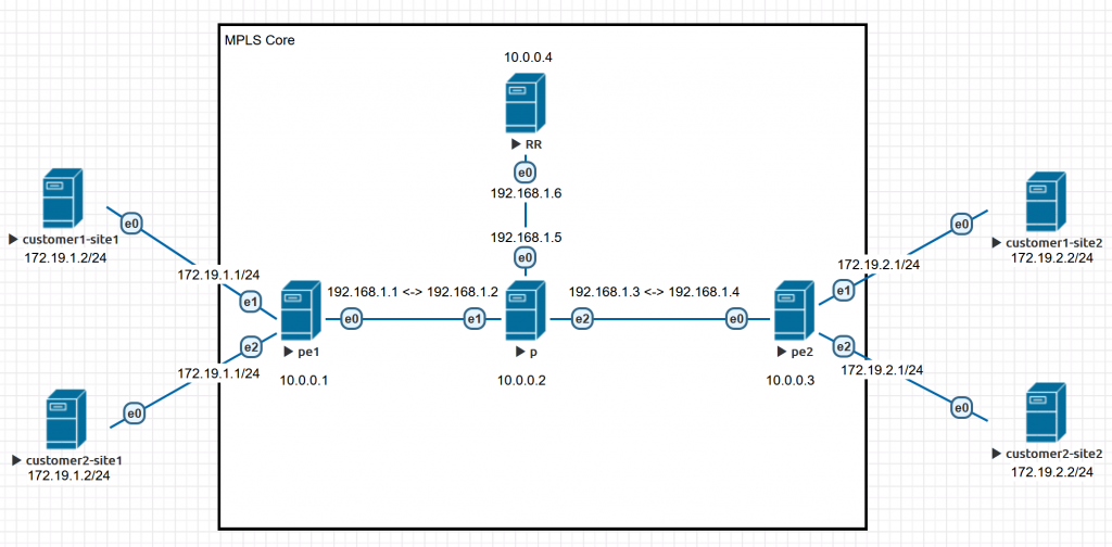
So here is our topology. Notes:
- All solid lines are Ethernet connections
- Connections between core routers use 192.168.1.0/24 in a point-to-point configuration
- All core routers have a 10.0.0.x/32 IP address configured on its loopback interface
- The e0/e1/e2 interfaces on this graph matches ens3/ens4/ens5 below in the commands respectively
The Problems We are not Solving for Now
To limit the length of this article, we are not discussing the following advanced topics:
- MTU mismatch problem (for simplicity, I recommend clamping MSS to 1410)
- Dynamic routing protocols between CE and PE
- Auto configuring of Linux network stack (all the configuration we use in this article will be lost after a reboot; how to use your favorite network manager to configure them on boot is an exercise left for readers)
- VPLS (a.k.a. MPLS L2VPN. Pseudowire interface is not supported by Linux by the time of writing)
My friend LittleWolf wrote an excellent article covering some topics I’ve left out: how to use IS-IS as the iBGP protocol in core, and how to configure BGP between CE and PE routers, all in a similar topology. Read it here: [ Linux ] 使用 Debian Linux 构架 MPLS L3 网络
Reference Software Setup
All devices we use run the following software:
- Debian 10 (Linux 4.19.0)
- iproute2 4.20.0
- FRRouting 7.2.1 (deb provided by FRRouting)
The Configuration
The first line of each code block describes which environment the following code should be typed in:
# linux shellmeans run it under a Linux native shell (bash, etc.)# vtyshmeans run it under vtysh# vtysh configmeans run it under vtysh config mode (conf t)
Setup Linux
Install FRRouting:
|
1 2 3 4 5 |
# linux shell curl -s https://deb.frrouting.org/frr/keys.asc | sudo apt-key add - echo deb https://deb.frrouting.org/frr buster frr-stable | sudo tee -a /etc/apt/sources.list.d/frr.list apt update apt install frr |
Launch FRRouting via systemd:
|
1 2 3 4 |
# linux shell sed -i "s/=no/=yes/g" /etc/frr/daemons systemctl enable frr systemctl restart frr |
Load MPLS kernel module:
|
1 2 3 4 5 6 7 8 9 10 11 |
# linux shell modprobe mpls_router modprobe mpls_iptunnel modprobe mpls_gso modprobe dummy cat >/etc/modules-load.d/mpls.conf <<EOF mpls_router mpls_iptunnel mpls_gso dummy EOF |
Initial config for MPLS kernel module:
|
1 2 3 4 5 6 7 8 9 10 11 |
# linux shell cat >/etc/sysctl.d/90-mpls-router.conf <<EOF net.ipv4.ip_forward=1 net.ipv6.conf.all.forwarding=1 net.ipv4.conf.all.rp_filter=0 net.mpls.platform_labels=1048575 net.ipv4.tcp_l3mdev_accept=1 net.ipv4.udp_l3mdev_accept=1 net.mpls.conf.lo.input=1 EOF sysctl -p /etc/sysctl.d/90-mpls-router.conf |
Core Network Layer 3 & Loopback IP Setup
Loopback IP address is not strictly necessary, but if you don’t configure it, you will need to set up source IP addresses for every protocol we need. Configuring a loopback IP address will make your life easier and prevents a lot of dark magic problems.
P
|
1 2 3 4 5 6 7 8 9 10 |
# linux shell ip link set ens3 up ip link set ens4 up ip link set ens5 up ip addr add 192.168.1.5 peer 192.168.1.6 dev ens3 ip addr add 192.168.1.2 peer 192.168.1.1 dev ens4 ip addr add 192.168.1.3 peer 192.168.1.4 dev ens5 ip link add dummy0 type dummy ip link set dummy0 up ip addr add 10.0.0.2/32 dev dummy0 |
PE1
|
1 2 3 4 5 6 7 8 |
# linux shell ip link set ens3 up ip link set ens4 up ip link set ens5 up ip addr add 192.168.1.1 peer 192.168.1.2 dev ens3 ip link add dummy0 type dummy ip link set dummy0 up ip addr add 10.0.0.1/32 dev dummy0 |
PE2
|
1 2 3 4 5 6 7 8 |
# linux shell ip link set ens3 up ip link set ens4 up ip link set ens5 up ip addr add 192.168.1.4 peer 192.168.1.3 dev ens3 ip link add dummy0 type dummy ip link set dummy0 up ip addr add 10.0.0.3/32 dev dummy0 |
RR
|
1 2 3 4 5 6 |
# linux shell ip link set ens3 up ip addr add 192.168.1.6 peer 192.168.1.5 dev ens3 ip link add dummy0 type dummy ip link set dummy0 up ip addr add 10.0.0.4/32 dev dummy0 |
Checking
You should be able to ping a router’s interface IP from its direct neighbor router.
Set Up IGP in the Core Network
The object here is to make all loopback IP addresses reachable from any point of your core network. Because I don’t know how to configure other protocols To simplify things, we use OSPF as an example and put all the routers in Area 0. Note that we configured all the Ethernet connections between routers as point-to-point links, so we need to manually set interface type here.
P
|
1 2 3 4 5 6 7 8 9 10 11 12 13 |
# vtysh config interface ens3 ip ospf network point-to-point interface ens4 ip ospf network point-to-point interface ens5 ip ospf network point-to-point router ospf ospf router-id 10.0.0.2 redistribute connected redistribute static network 10.0.0.0/24 area 0 network 192.168.1.0/24 area 0 |
PE1
|
1 2 3 4 5 6 7 8 9 |
# vtysh config interface ens3 ip ospf network point-to-point router ospf ospf router-id 10.0.0.1 redistribute connected redistribute static network 10.0.0.0/24 area 0 network 192.168.1.0/24 area 0 |
PE2
|
1 2 3 4 5 6 7 8 9 |
# vtysh config interface ens3 ip ospf network point-to-point router ospf ospf router-id 10.0.0.3 redistribute connected redistribute static network 10.0.0.0/24 area 0 network 192.168.1.0/24 area 0 |
RR
|
1 2 3 4 5 6 7 8 9 |
# vtysh config interface ens3 ip ospf network point-to-point router ospf ospf router-id 10.0.0.4 redistribute connected redistribute static network 10.0.0.0/24 area 0 network 192.168.1.0/24 area 0 |
Checking
Any router’s loopback IP address should be pingable from any other router in the core network. For example we ping RR from PE1:
|
1 2 |
# linux shell ping -I 10.0.0.1 10.0.0.4 |
Enable MPLS processing and LDP service
Every core-facing interface should enable MPLS processing and enable LDP protocol:
P
|
1 2 3 4 |
# linux shell sysctl net.mpls.conf.ens3.input=1 sysctl net.mpls.conf.ens4.input=1 sysctl net.mpls.conf.ens5.input=1 |
|
1 2 3 4 5 6 7 8 |
# vtysh config mpls ldp router-id 10.0.0.2 address-family ipv4 discovery transport-address 10.0.0.2 interface ens3 interface ens4 interface ens5 |
PE1
|
1 2 |
# linux shell sysctl net.mpls.conf.ens3.input=1 |
|
1 2 3 4 5 6 |
# vtysh config mpls ldp router-id 10.0.0.1 address-family ipv4 discovery transport-address 10.0.0.1 interface ens3 |
PE2
|
1 2 |
# linux shell sysctl net.mpls.conf.ens3.input=1 |
|
1 2 3 4 5 6 |
# vtysh config mpls ldp router-id 10.0.0.3 address-family ipv4 discovery transport-address 10.0.0.3 interface ens3 |
RR
RR doesn’t really need to be practicing this MPLS network here; it only needs to be able to reach all the PEs. But current LDP daemon implementation of FRRouting does not support Downstream Unsolicited mode so we are left with the only option of Downstream-on-Demand mode. In this mode, if you enable IGP on the RR but do not enable MPLS on it, packets going from PE to RR will be discarded at P because P doesn’t have an entry for RR in its MPLS switching table. Again, to make things simple, we enable MPLS on the RR too:
|
1 2 |
# linux shell sysctl net.mpls.conf.ens3.input=1 |
|
1 2 3 4 5 6 |
# vtysh config mpls ldp router-id 10.0.0.4 address-family ipv4 discovery transport-address 10.0.0.4 interface ens3 |
If you really doesn’t want to run MPLS on the RR, there is another option: do not enable IGP on the RR, write a static route to RR on its neighbor P or PE router and redistribute that static route. The third option is to use label local allocate for to force LDP allocate a label for the prefix to RR.
Checking
All adjacent routers should have LDP session established. For example, on the P:
|
1 2 3 |
# vtysh show mpls ldp neighbor |
You should see 3 LDP sessions:
|
1 2 3 4 |
AF ID State Remote Address Uptime ipv4 10.0.0.1 OPERATIONAL 10.0.0.1 09:40:33 ipv4 10.0.0.3 OPERATIONAL 10.0.0.3 09:40:01 ipv4 10.0.0.4 OPERATIONAL 10.0.0.4 08:18:28 |
Plus all core routers should still be able to ping each other’s loopback IP. (These pings are now going through MPLS network rather than IP network. That’s a sign that your MPLS network is working.)
Configuring iBGP on PEs
iBGP only needs to be configured on PEs but not Ps. This is one of MPLS’s benefits: core routers only need to process label switching but do not need to store and update routing tables. You can use either a full mesh iBGP setup or a Route Reflector; we have a RR on the topology, so we are sticking to the RR method. To simplify things, I’m only demonstrating IPv4 config (disable IPv4 unicast SAFI, enable IPv4 VPNv4 SAFI); if you need IPv6 inside MPLS then repeat the config for IPv6.
In a production environment, a single RR instance is a single point of failure. Packet Pusher authored a good article about RR redundancy architecture designing for reference.
RR
|
1 2 3 4 5 6 7 8 9 10 11 12 |
# vtysh config router bgp 65000 no bgp default ipv4-unicast neighbor 10.0.0.1 remote-as 65000 neighbor 10.0.0.1 update-source dummy0 neighbor 10.0.0.3 remote-as 65000 neighbor 10.0.0.3 update-source dummy0 address-family ipv4 vpn neighbor 10.0.0.1 activate neighbor 10.0.0.1 route-reflector-client neighbor 10.0.0.3 activate neighbor 10.0.0.3 route-reflector-client |
PE1 and PE2
|
1 2 3 4 5 6 7 |
# vtysh config router bgp 65000 no bgp default ipv4-unicast neighbor 10.0.0.4 remote-as 65000 neighbor 10.0.0.4 update-source dummy0 address-family ipv4 vpn neighbor 10.0.0.4 activate |
Checking
All BGP sessions should come up.
Configure VRF instances on PE routers
There are 2 ways to implement VRF on Linux, net namespace and VRF interface. Net namespace is a network stack abstraction unique to the Linux kernel, it provides complete isolation which is useful for paravirtualization and containers, but it also prevents route leaking and data exchange so we are not going to use it. VRF interface is more like the VRF you would see on a commercial router system, since we are only using Linux as a router, we choose this method.
The config is quite simple. Every VRF interface will be associated to a routing table identified by its table ID during creation. Then you can add routed interfaces to a VRF just like how you add a switched port to a bridge. To make the new routing table available to an application, here we will add an unreachable default route with its metric set to the max value.
To prevent human errors, we use the same VRF name and table ID for the same customer on every PE router.
PE1
|
1 2 3 4 5 6 7 8 9 10 11 12 13 14 15 16 17 18 19 |
# linux shell # customer 1 ip link add customer1 type vrf table 100 ip link set customer1 up ip route add vrf customer1 unreachable default metric 4278198272 ip -6 route add vrf customer1 unreachable default metric 4278198272 ip link set ens4 vrf customer1 ip link set ens4 up ip addr add 172.19.1.1/24 dev ens4 # customer 2 ip link add customer2 type vrf table 200 ip link set customer2 up ip route add vrf customer2 unreachable default metric 4278198272 ip -6 route add vrf customer2 unreachable default metric 4278198272 ip link set ens5 vrf customer2 ip link set ens5 up ip addr add 172.19.1.1/24 dev ens5 |
PE2
|
1 2 3 4 5 6 7 8 9 10 11 12 13 14 15 16 17 18 19 |
# linux shell # customer 1 ip link add customer1 type vrf table 100 ip link set customer1 up ip route add vrf customer1 unreachable default metric 4278198272 ip -6 route add vrf customer1 unreachable default metric 4278198272 ip link set ens4 vrf customer1 ip link set ens4 up ip addr add 172.19.2.1/24 dev ens4 # customer 2 ip link add customer2 type vrf table 200 ip link set customer2 up ip route add vrf customer2 unreachable default metric 4278198272 ip -6 route add vrf customer2 unreachable default metric 4278198272 ip link set ens5 vrf customer2 ip link set ens5 up ip addr add 172.19.2.1/24 dev ens5 |
Redistribute Customer Routers to VRF Routing Tables
This article is way too long as what I expected, so we are going to redistribute connected route only just to keep things simple. Dynamic routing protocols between PE and CE routers can be configured in the same way. In this step, you need to create an empty BGP configuration on every VRF, import all the routes you need to redistribute to that BGP instance’s RIB, add a route distinguisher community to the route, then import it to the main BGP instance’s RIB.
To prevent human error, we use the same RT and RD as the table ID for every customer, but you need to be aware that they can all be different if required. Another thing you need to remind yourself is that although FRRouting vtysh tried hard to mimic a grammar like the Cisco IOS, they still differ in some way.
PE1 and PE2
|
1 2 3 4 5 6 7 8 9 10 11 12 13 14 15 16 17 18 19 |
# vtysh config router bgp 65000 vrf customer1 address-family ipv4 unicast redistribute connected redistribute static label vpn export auto rd vpn export 65000:100 rt vpn both 65000:100 export vpn import vpn router bgp 65000 vrf customer2 address-family ipv4 unicast redistribute connected redistribute static label vpn export auto rd vpn export 65000:200 rt vpn both 65000:200 export vpn import vpn |
When you are typing the config, FRRouting will alert you about some error; don’t panic and continue.
Checking
Now we should see connected routes redistributed by BGP in every VRF of every PE. For example, on PE1:
|
1 2 |
# vtysh show ip bgp vrf customer1 |
You should see something like this:
|
1 2 3 4 5 6 7 8 9 10 11 12 |
BGP table version is 2, local router ID is 172.19.1.1, vrf id 9 Default local pref 100, local AS 65000 Status codes: s suppressed, d damped, h history, * valid, > best, = multipath, i internal, r RIB-failure, S Stale, R Removed Nexthop codes: @NNN nexthop's vrf id, < announce-nh-self Origin codes: i - IGP, e - EGP, ? - incomplete Network Next Hop Metric LocPrf Weight Path *> 172.19.1.0/24 0.0.0.0 0 32768 ? *> 172.19.2.0/24 10.0.0.3@0< 0 100 0 ? Displayed 2 routes and 2 total paths |
Configure Customer Site
To simulate a case where different customers’ IP ranges overlap, we configure the same IP address on the two customer’s router on the same side.
customer1-site1 and customer2-site1
|
1 2 3 4 |
# linux shell ip link set ens3 up ip addr add 172.19.1.2/24 dev ens3 ip route add default via 172.19.1.1 |
customer1-site2 and customer2-site2
|
1 2 3 4 |
# linux shell ip link set ens3 up ip addr add 172.19.2.2/24 dev ens3 ip route add default via 172.19.2.1 |
Checking
The first thing you need to check is the routers of the same customer pings fine. As we have PHP and TTL propagation enabled, 3 MPLS hops in the core will result in 2 hops of non-IP routing. So, if you use traceroute or mtr, you’ll see something like this:
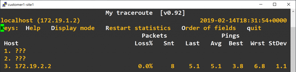
Sadly, Linux only support RFC4884 partially and doesn’t support RFC4950 at the time of writing, so traceroute -e and mtr --mpls is not going to help you at all.
Next, we need to verify that we do correctly connected the sites of the same customer. To do this we use netcat to simulate a simple TCP chat service. Start the server on one of the customer sites:
|
1 2 |
# linux shell nc -l -p 8888 |
And connect to the server on another site of the same customer:
|
1 2 |
# linux shell nc 172.19.2.2 8888 |
After a successful connection, you can type anything into both the server and the client, press enter, and the message should be sent to the other side.
MPLS…
The whole story of Linux development can be summed up in one story: someday you want to make a model plane, so you built one using sticks and paper in the backyard. The next day when you woke up, you are surprised to find that the model plane is already in the sky flown by your neighbor carrying tens of passengers, and there are two people standing on the wings trying to fix the engine and maintain balance as well.
“It is provided free of charge, and if it fails, I won’t be hurt, so why to bother?” And you went on your daily work.
Thanks:
Two CCIE certified friends helped a lot during the writing of this article.
References:
- Virtual Routing and Forwarding: Cumulus Linux
- VRF for Linux — a contribution to the Linux Kernel
- Using the Linux VRF Solution
- Configuring a VRF to work properly for FRR
- iproute2 commands for MPLS configuration
- LDP: FRRouting
- ldpd basic test setup
- frrouting/linux bgp mpls example
- LDP: Label allocation for “not connected” IP Prefix.
- BGP: FRRouting
- End-to-End MPLS Not Working On Docker Container
- Inconsistency in auto-derived RT value of EVPN show commands.
- MPLS及LDP协议基础
- MP-EBGP Configuration Example
- MPLS: Layer 3 VPNs Configuration Guide, Cisco IOS Release 15M&T
- Configuring a Basic MPLS VPN
- Troubleshooting Any Transport over MPLS Based VPNs
- How to Create a Simple Chat with netcat in Linux